KAZAKH INVENTORS DESIGNED A WIND WHEEL EXCEEDING THE CAPACITY OF STRAIGHT AXIS BLADES BY 2-3 TIMES
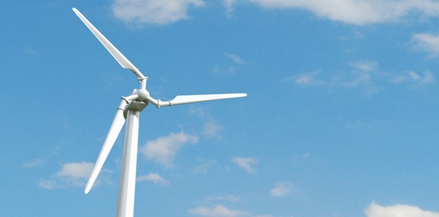
The principal element of the wind power plant for converting kinetic energy of a wind stream is presented by the design features of the wind wheel.
The deficiency of traditionally used wind wheels is in their direct power of rotation at the main shaft of the wind turbine, which requires lengthening the blades in order to increase the capacity of the wind turbine. As such, traditionally used rotors have reached their technical limits (the length of the blade is more than 60 meters and the mass exceeds 7 tons).
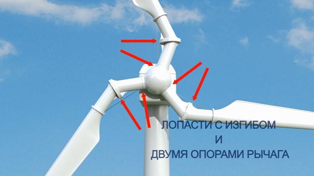
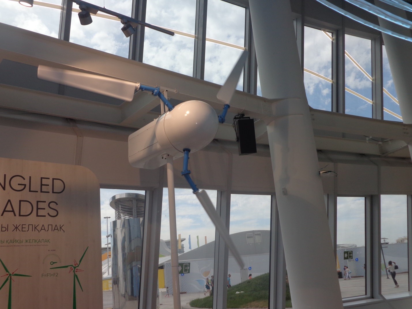
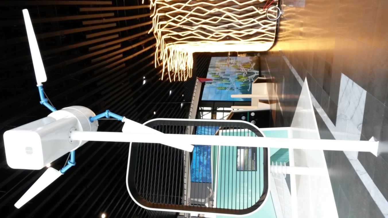
Kazakh inventors Shaikenov B. and Shaikenov E.B. designed the new form of the wind wheel. The blade in the invented rotor design consists of two parts: a short root part with an elbow bend and a long wing-shaped part. The short root part of the blade is divided into an axial segment, which is secured to the hub mounted on the main shaft of the wind turbine and a sleeve segment, connected at 30-600 angle, thereby creating the elbow bend. The long wing-shaped part is connected to the sleeve segment through swiveling devices.
This new design feature creates effective wind current kinematics with high wind capture coefficient, due to special design of lever-shaped blades with two force application fulcrums and two points of force application on one side.
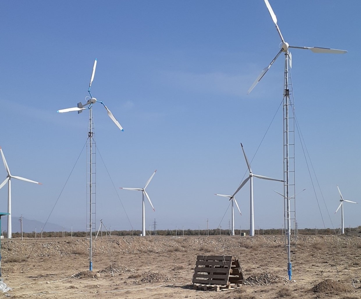
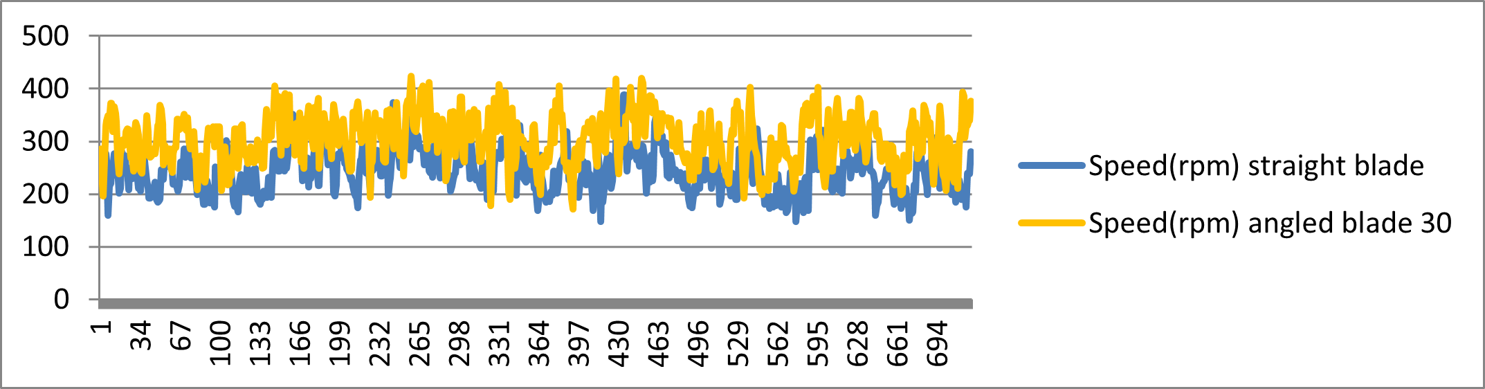
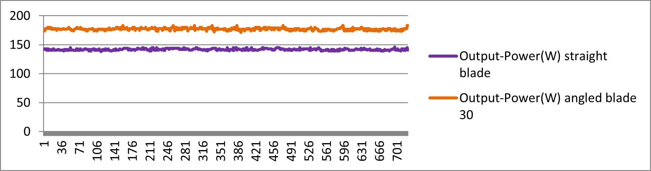
During simultaneous testing of the wind wheel with blades of the invented construction and the wind wheel with straight axis blades at “Kapchagai” polygon, under the conditions of equal force wind stream, the new wind turbine showed higher velocity of rotation by 0.5 to 3.5 times faster, than the straight axis turbine. The electricity generated was also correspondingly greater.
The invention opens up new horizons for wind power generation. It increases the coefficient of rotational force of the wind stream and allows using more powerful energy generators. The invention also allows reducing the blade’s length and decreasing the weight of the nacelle and the tower, thereby, increasing generation of annual unit of electrical power per unit of swept area, and reducing the cost of kilowatt-hour of energy for materials consumed and its construction.
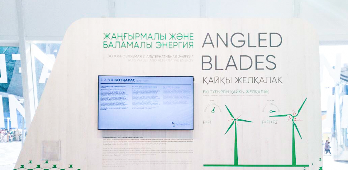
WIND WHEEL WITH ANGLED BLADES — THE FUTURE OF WIND ENERGY INDUSTRY
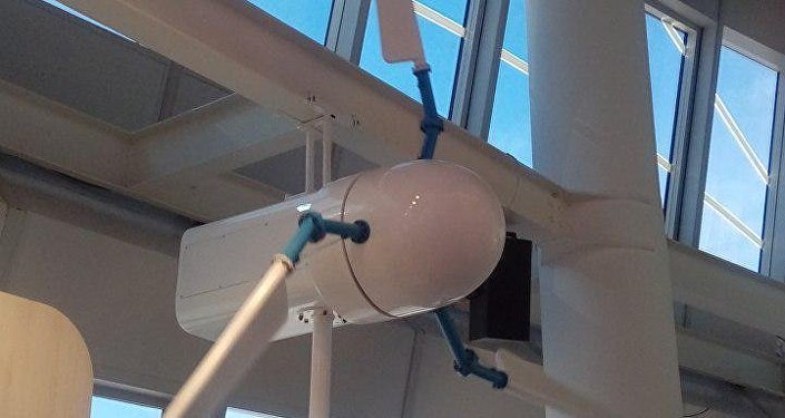
The model of the wind wheel with angled blades is demonstrated at the “Best Practices” on the first floor opposite the “Nur-Alem” sphere from the northern part.
The wind wheel is a lever. Currently, design improvements of the rotor have reached the limits of technical feasibility (blade length up to 80-112 meters, weight more than 7 tons).
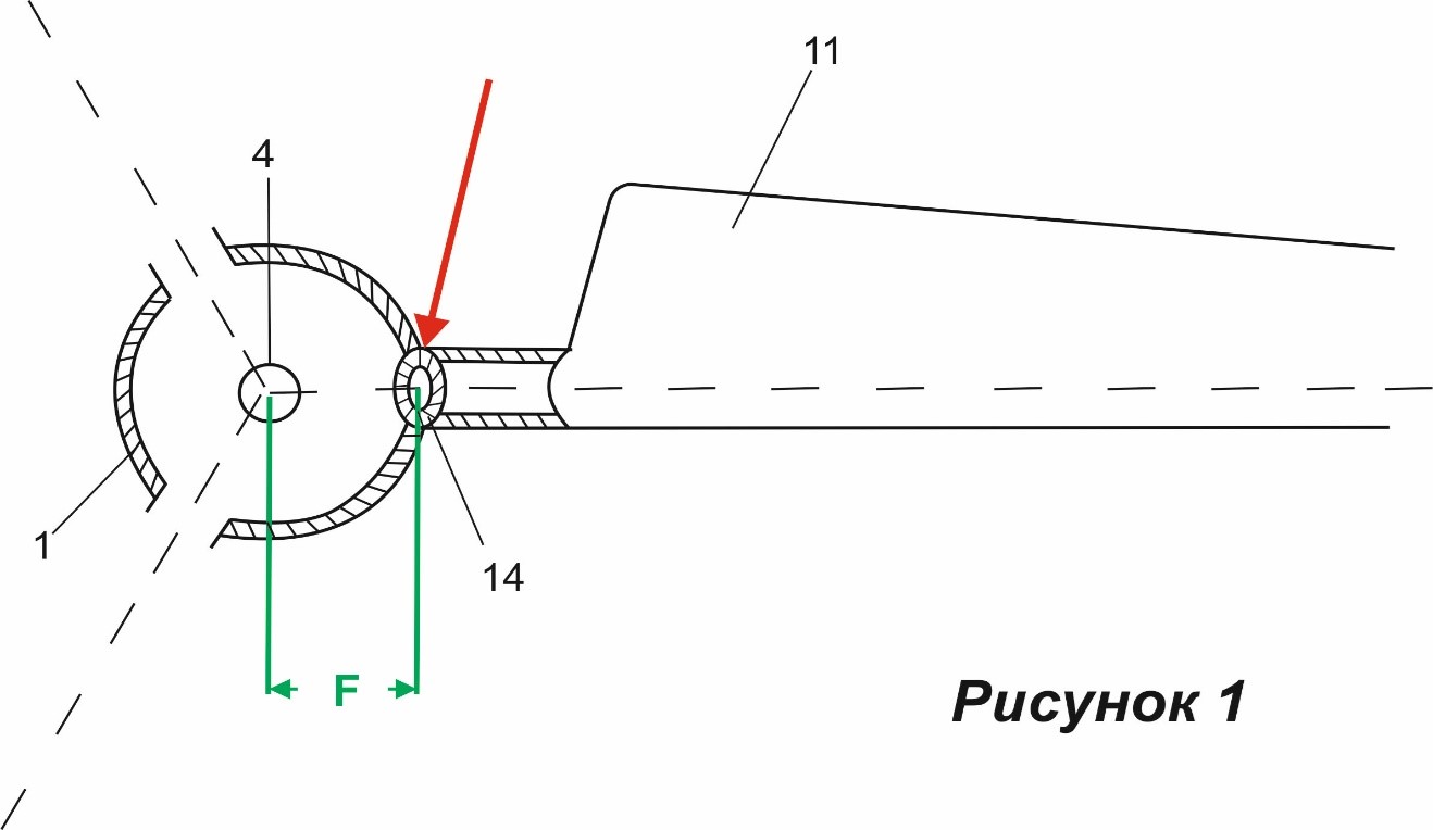
The basis of traditionally used wind wheels is the direct power rotation of the main shaft of the wind engine. The transfer of kinetic wind force from the blade occurs through the point of its attachment to the installation head and the force F of the lever is equal to the distance between the fulcrum point and the center of the main shaft (fig. 1).
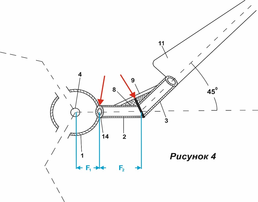
In our design of the rotor “Angled blade”, the blade has a shape like a hockey stick (fig. 2). In the invented design of the rotor, the blade consists of two parts: a short root part with a knee bend (fig. 2.2; 2.3) and a long wing-shaped (fig. 2.11) part.
What are the advantages of our design over traditional straight axis blades?
The new design of the wind blade uses the power of the lever, creates an efficient kinematics of the wind flow with a high coefficient of action. In the “Angled blade” design, the moment of force F1 is additionally enhanced with the addition of the axial section F2 to it. The axial section of the short part of the blade is the link that makes up the moment of additional force (F = F1 + F2). The reported additional force is proportional to the increase in the length of the axial section (F2), which, depending on the designed power of the wind turbine, is 0.20-5 m.
The technical results of the invention are:
- increasing the efficiency factor of wind energy, increasing the power of the wind generator, reducing the consumption of materials by reducing the length of the blades, reducing the weight of the gondola and wind turbine support;
- Reducing the cost of electricity generated by wind power plants, reducing environmental pollution from thermal power plants and nuclear reactors, which will ultimately make wind power more competitive compared to other energy sources.
Patents acquired. Based on the results of design research, 6 patents of Kazakhstan and 2 patents of the European Patent Organization were obtained, on the basis of which national patents were obtained from 8 European countries: Germany, Denmark, the United Kingdom, the Netherlands, France, Spain, Turkey, Russia, as well as patents from Japan, South Korea, India, China and the USA.
Field tests.The wind wheel "Angled blade" was tested in comparison with a rotor with straight blades at wind ranges near the cities of Kapchagay and Nurly (Enbekshikazakh district) in Kazakhstan in 2017-2020. An AeroCraft 750 generator (manufactured in Germany) was used to test the Angled blade rotor and the straight blade rotor.
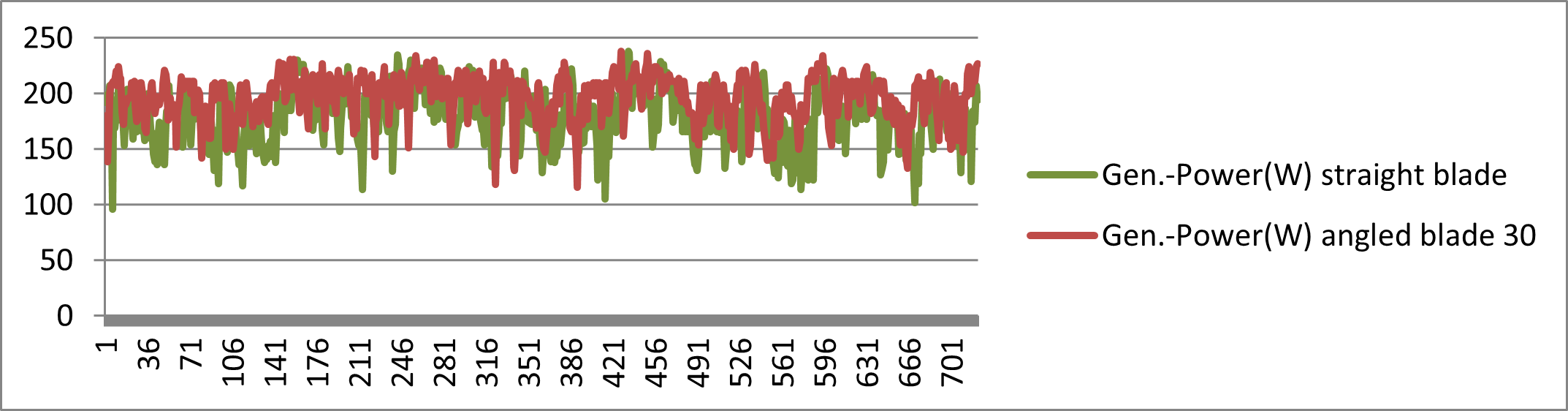
The dynamic indicators of the generators: electricity generation, rotational speed, battery charging and power output were recorded daily through the ACLR controller in the computer using the Excel program.
At a wind speed of 5-6 m/sec, the electricity generation and rotational speed of the Angled blade rotor exceeds the rotor with straight blades by 15-17%, then at a wind speed of 8-9 m/sec this difference can reach 25-30%, and at wind flow speeds over 11-13 m/sec, the differences in these indicators increase to 50-70%.
Demonstration. The model of our design as the best innovation of Kazakhstan was selected for display at EXPO-2017 in the Best Practice Pavilion, currently located in the World Pavilion of EXPO in Astana city, Kazakhstan, on the 5th floor of Wind energy exhibition.
Authors
B.Shaikenov E.B.Shaikenov